Atmel Ice Green Led Goes Away Reading Target
Debugging SAM-Based Arduino® Boards with Atmel-Ice
Learn how to debug SAM-based Arduino boards using the Atmel-Ice debugger and the Arduino IDE 2.0
Introduction
In this tutorial, we will learn how to use the Atmel-ICE development tool with the new Arduino IDE 2.0 for debugging SAM-based Arduino® boards. Using an Arduino MKR WiFi 1010 board and a simple program, we volition learn nearly the debugging functionalities that are integrated with the debugger tool of the new IDE 2.0.
Goals
The goals with this tutorial are:
- Learn how to utilize an Atmel-ICE development tool with the new Arduino IDE ii.0 and a SAM-based Arduino® board.
- Learn about the debugging functionalities of the new Arduino IDE 2.0.
Hardware and Software Needed
The hardware and software used in this tutorial:
- Arduino IDE two.0.
- Arduino MKR WiFi 1010 board.
- Atmel-ICE evolution tool.
- ten-pin mini-squid cable (included with the Atmel-ICE evolution tool)
- Micro USB cablevision (x2).
- 2.54mm correct-angle male headers (x6).
- ii.54mm direct male person headers (x6 - optional).
- MKR Proto Shield (optional).
- Soldering atomic number 26, or a soldering station, and solder.
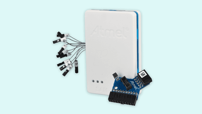
Atmel-Ice is a powerful evolution tool that tin exist used for debugging and programming ARM ® Cortex ® -Thou-based SAM and AVR microcontrollers with on-bit debug capability. 1 of the master features of Atmel-ICE is its back up of several debugging/programming interfaces like JTAG, SWD, PDI, TPI, aWire, SPI, debugWIRE, and UPDI. For debugging SAM-based Arduino ® boards with the Atmel-ICE, we are going to use its SWD interface.
The SWD Interface
JTAG is the de facto interface for debugging and accessing a processor registers. This interface has been used for many years, and it is still largely used today. Simply JTAG has a drawback: it uses many signals (or pins), at to the lowest degree iv. To accost this drawback, ARM® created an alternative debug interface chosen the Serial Wire Debug (SWD) interface.
The SWD interface is a two-pin (SWDIO/SWCLK) electric alternative to the JTAG interface that has the same JTAG protocol on top. The SWD interface can exist used to programme the firmware of a processor and access its registers for debugging purposes. This interface and its associated protocol are at present available in nearly all ARM® Cortex®-A, Cortex®-R, and Cortex®-M processors.
Preparing the SWD Interface
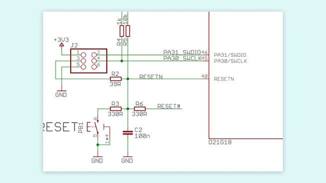
Earlier we connect the Atmel-ICE development tool to our Arduino® MKR WiFi 1010 board, we have to fix the SWD interface pins of our board. The MKR WiFi 1010 lath has the SWD interface pins, SWDIO and SWCLK, connected to the J2 header as shown in its schematic.
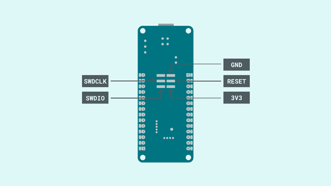
The J2 header pins of the MKR WiFi 1010 board are located on the underside of the board in the exposed pads; the pinout is shown in the image beneath:
There are several methods to connect the J2 header pins of the MKR WiFi 1010 board to the SWD interface of the Atmel-ICE development tool. For case, one method can be soldering wires directly on the exposed pads; in this tutorial, we are going to explain how to set up two dissimilar methods: one that requires soldering and one that doesn't.
Annotation: The goal is to reach the exposed pads that are located on the underside of the board, experience free to choose one of the two methods that are explained in this tutorial or to implement another solution not mentioned hither.
In the first method, the one that requires soldering, half-dozen 2.54mm right-angle male person headers are soldered on the exposed pads every bit shown in the prototype below:
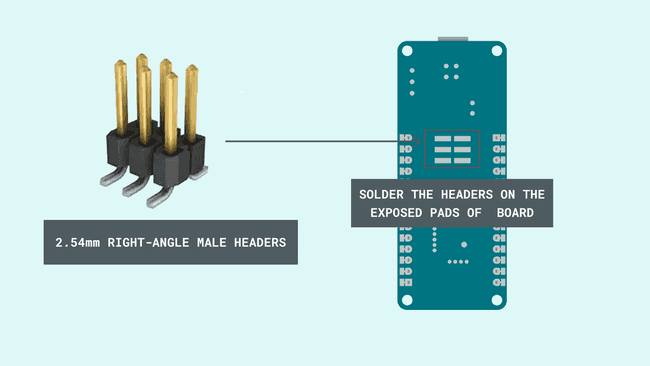
Now you can connect the mini-squid cablevision to the soldered right-angle headers. Notice that, while the headers are soldered to the exposed pads of the MKR WiFi 1010 board, you are not going to exist able to use the lath in a breadboard because it won't fit.
Method 2: Using a MKR Proto Shield and Headers
In the 2d method, the 1 that doesn't requires any soldering, a MKR Proto Shield and 6 two.54mm straight male headers can exist used to access the exposed pads of the MKR WiFi 1010 board as shown in the images below:
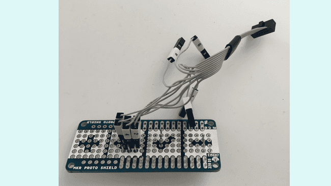
Besides not requiring whatsoever soldering, with this method the MKR Proto Shield remains too fully reusable. At present you lot can connect the mini-squid cablevision to the straight headers in the shield.
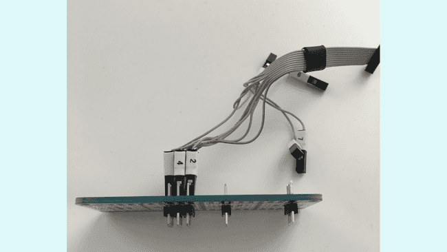
Connecting the Atmel-ICE to the MKR WiFi 1010
Now that we have the MKR WiFi 1010 board SWD interface, nosotros can connect it to the Atmel-ICE SWD interface. The Atmel-Water ice development tool has two ports: an AVR and a SAM port. We tin employ both ports to admission the SWD interface pins; the required connections are described in the table below:
| Name | AVR Port Pin | SAM Port Pin | Clarification |
|---|---|---|---|
| SWDCLK | 1 | 4 | Series Wire Debug Clock. |
| SWDIO | 5 | ii | Series Wire Debug Information Input/Output. |
| SWO | 3 | half-dozen | Series Wire Output (optional). |
| nSRST | 6 | 10 | Reset. |
| VTG | 4 | 1 | Target voltage reference. |
| GND | 2, 10 | 3, five, 9 | Ground. |
We used the SAM port in this tutorial; this means nosotros used the pins iv, two, half dozen, ten, ane and 3 (just one GND connectedness is enough) of the SAM port.
Note: be conscientious and double-check the connections betwixt the Atmel-Water ice and the MKR WiFi 1010 board SWD interfaces to avoid damaging one or both devices.
If the SWD interfaces of the debugger and the board are connected properly, a light-green LED should turn on in the debugger. At present that we accept both devices, the Atmel-Ice and the MKR WiFi 1010 board, SWD interfaces connected, its time to use the debugger tool of the Arduino IDE two.0.
Now that we have our hardware ready, nosotros tin can learn how to use the IDE 2.0 Debugger Tool main functionalities through the Debugging with the Arduino IDE 2.0 tutorial. This tutorial goes through some key features of the Debugger Tool, and includes pointers to get started.
Every bit explained in the Debugging with the Arduino IDE 2.0 tutorial, before we can employ the Debugger Tool of the Arduino IDE 2.0, we demand to upload a sketch to our MKR WiFi 1010 lath, making certain it is optimized for debugging. Permit's try a unproblematic plan that blinks the onboard LED of our MKR WiFi 1010 board and changes the value of several variables while running.
1. Setting Up
Let's start past opening the Arduino IDE 2.0 and connecting our MKR WiFi 1010 board to our computer with a micro USB cable. The IDE should recognize automatically the board, if so, the board and port should announced every bit shown in the image beneath:

2. Creating the Examination Lawmaking
Permit's try the example code show below, it is a simple program that blinks the onboard LED of our board and changes the value of variables
x and
y while running. Open a new sketch, copy and paste the code evidence below:
1 /*
2 Elementary Debugger Test
3
four This example blinks the onboard LED of an Arduino board and changes
5 the value of the variables 10 and y wwhile running. The purpose of
6 this example is to test the debugging functionalities of the Arduino
7 IDE 2.0.
8
9 The circuit:
x - Arduino MKR WiFi 1010
11
12 Created by José Bagur
13
14 This instance code is in the public domain.
15 */
xvi
17 // Initialize variables x and y
18 int x = 0 ;
19 int y = 0 ;
xx
21 void setup ( ) {
22 // Initialize digital pin LED_BUILTIN as an output
23 pinMode ( LED_BUILTIN , OUTPUT ) ;
24 }
25
26
27 void loop ( ) {
28 digitalWrite ( LED_BUILTIN , High ) ; // Turn the LED on
29 x ++ ; // Increment in one unit of measurement x
30 y -- ; // Decrement in one unit y
31 delay ( 1000 ) ; // Expect for a second
32
33 digitalWrite ( LED_BUILTIN , LOW ) ; // Turn the LED off
34 delay ( 1000 ) ; // Wait for a second
35 }
Earlier uploading the code to our board, we must optimize it for debugging. This can be fabricated easily by clicking on the Sketch tab and then selecting the choice Optimize for Debbuging:

With the Optimize for Debugging option selected, now its fourth dimension to upload the code to our board and start debugging it.
three. Using the Debugger Tool with the Exam Code
We can easily access to the Debugger Tool menu from the left sidebar of the Arduino IDE 2.0 where we can find also the Board Director, Library Manager, Search and Sketchbook Explorer.

Now, we tin can see the Debugger Tool carte du jour expanded. Allow's outset using the debugger tool past selecting the Start Debugging button that is located near the Upload button:

We should come across some text in the IDE panel from the Debugger Tool. The text displayed in the console shows data virtually the current debugging session, the debugging hardware tool and the connected board; for example, the board's microcontroller office number should be recognized by the Debugger Tool as shown below:
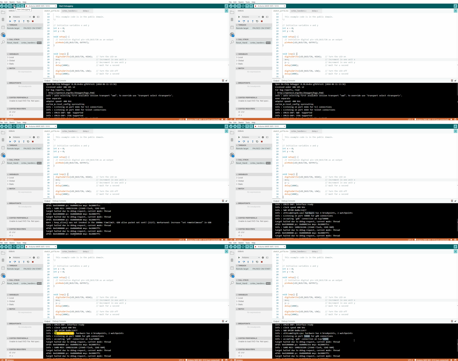
Let'due south fix ii breakpoints in lines 28 and 33. The breakpoints can be set in the Debugger Tool by clicking to the left of the line numbering in the editor as shown below:
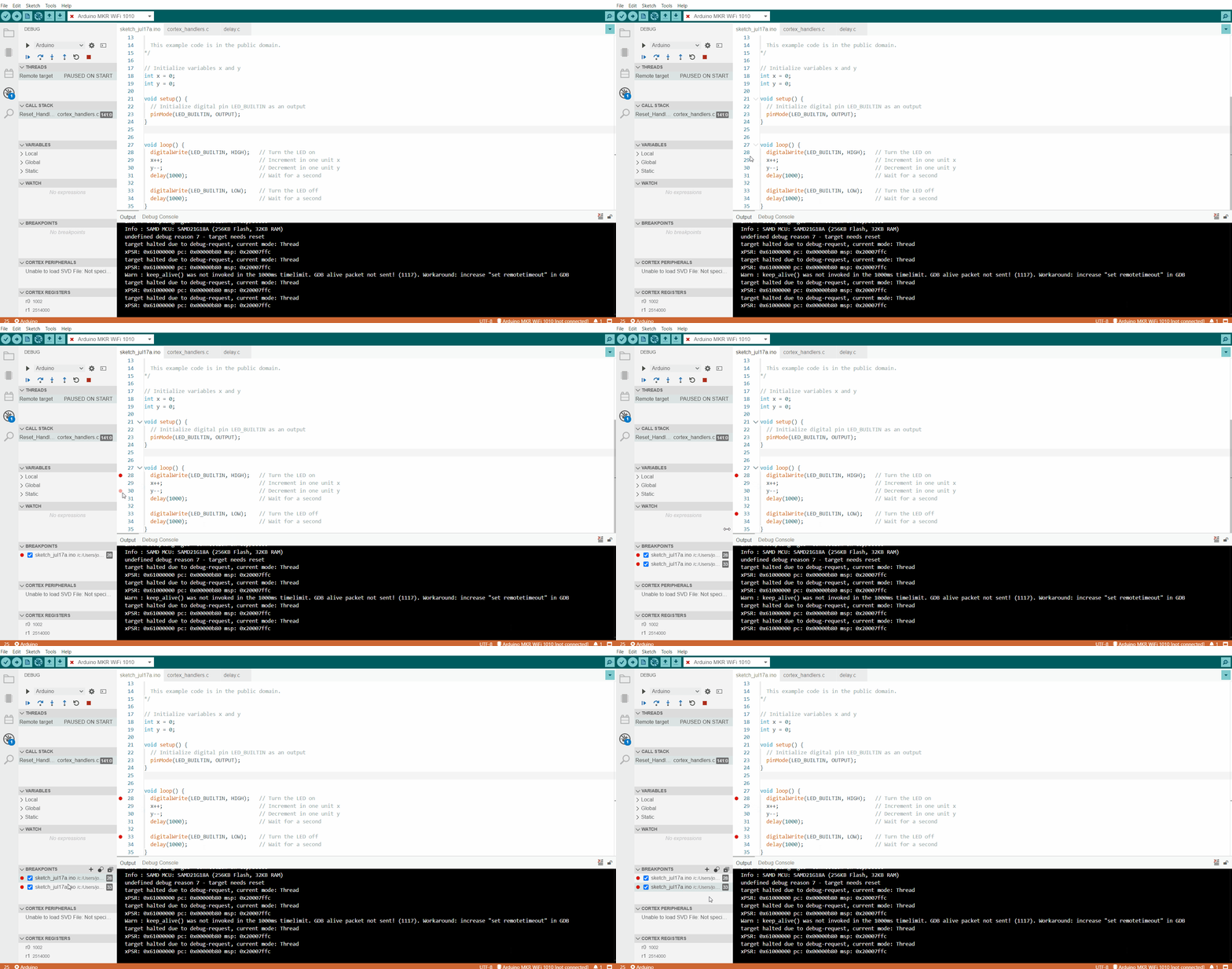
We should see now information virtually the breakpoint nosotros created in the Debugger Tool carte du jour. Let's also watch what is happening with variables
ten and
y in the program. To watch this variables we must add them in Watch section of the Debugger Tool as shown below:
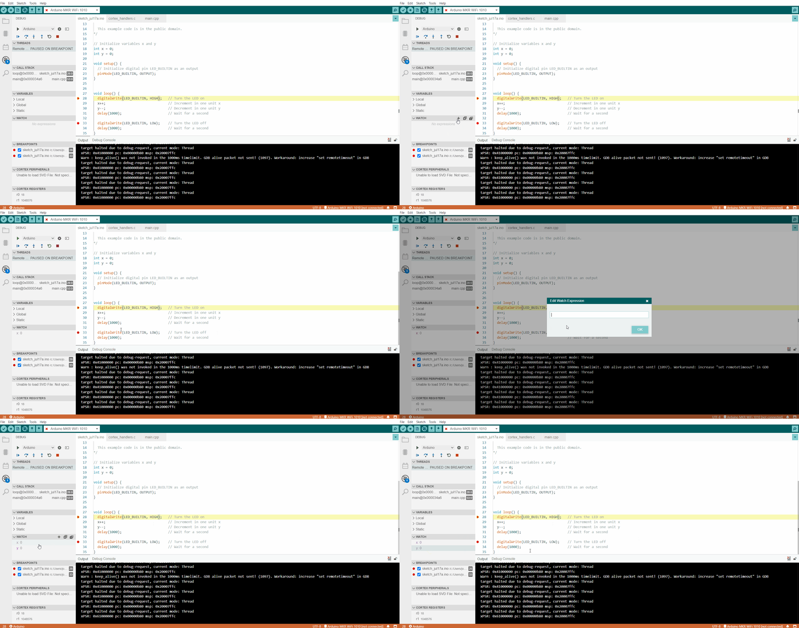
Now let's see what happens with the breakpoints and the ten and y variables in the Sentinel department of the Debugger Tool. Let's utilize the Continue push button, the program should run to the set breakpoints every time we press the Continue button as shown below, notice the value of x and y:
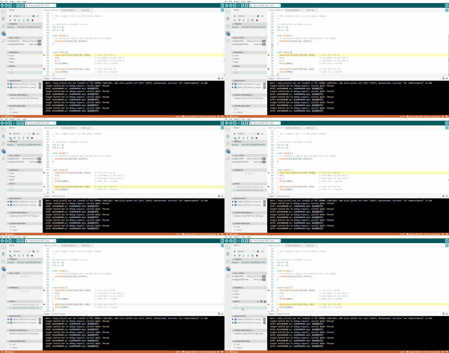
Every bit expected, we can see that the value of x increases in one unit while the value of y decreases in i unit. Also nosotros can see the onboard LED going on and off.
Determination
In this tutorial, we have learned how to utilize the Atmel-ICE development tool with the new Arduino IDE 2.0 for debugging SAM-based Arduino® boards. We larn how to connect the SWD interface of the Atmel-ICE evolution tool with the SWD interface of a MKR WiFi 1010 lath. With a simple plan, nosotros learned also about the debugging functionalities of the debugger tool of the new Arduino IDE 2.0.
Troubleshoot
Sometimes errors occur, there are some common issues we can troubleshoot:
- Missing a bracket or a semicolon in the code.
- Arduino lath connected to the wrong port.
- Adventitious interruption of cable connection of the board or the debugger.
- SWD interfaces of the debugger hardware tool and the lath are non continued properly.
- The debugging session in the IDE 2.0 didn't initialize correctly.
We hope yous enjoy the Debugger, and if you are having bug, please report them in Arduino IDE GitHub repository.
Source: https://docs.arduino.cc/tutorials/mkr-wifi-1010/atmel-ice
0 Response to "Atmel Ice Green Led Goes Away Reading Target"
Post a Comment